Introduction
When a milling job runs slow or tools fail early, the blame usually lands on machine horsepower or tooth material. But the geometry behind the cutting edge, and the direction that edge moves through the surface, matters just as much.
Wedge angle determines how a tooth penetrates asphalt, concrete, or reinforced pavement, and how well it survives under load. Rolling cutting action changes how that force transfers into the material, compared with a tool that strikes, slides, or scrapes.
This article breaks down rake, clearance, and wedge angles, explains the difference between sliding and rolling contact, and shows contractors how to apply these concepts when evaluating milling tools for their next job.
Key Takeaways
- Wedge angle, rake angle, and clearance angle form one geometry system; changing one shifts the other two.
- Sharper edges cut with less resistance but wear faster under heavy or abrasive loads.
- Rolling-wedging-lifting action differs from tools that strike, slide, or scrape through material.
- Tool selection depends on material, reinforcement, cut depth, machine compatibility, vibration, and desired finish.
Cutting Tool Geometry: The Angles That Shape the Cut
Every cutting tool, whether it's a single lathe bit or a milling tooth on a road-planer drum, has four basic reference features:
- Cutting edge: where the rake face meets the flank
- Rake face: the surface material flows across as it's removed
- Flank (clearance face): the surface behind the edge that trails the newly cut surface
- Reference plane: the fixed plane engineers use to measure every angle around the edge
The ISO 3002-1 standard defines all three working angles against these features. Rake, clearance, and wedge angle sum to 90 degrees, but only when measured in the same plane. An angle quoted without its reference plane is an incomplete number.
Rake Angle: Directing the Material Flow
Rake angle governs how material peels away from the edge:
- Positive rake: face angled away from the material, creating a sharper edge with lower cutting resistance
- Neutral rake: face roughly perpendicular to material flow
- Negative rake: face angled into the material, adding bulk behind the edge
Clearance Angle: Keeping the Flank Off the Surface
Clearance angle opens space between the flank and the freshly cut surface. Too little clearance, and the flank rubs against the new surface, generating heat and accelerating wear. Too much clearance, and there's not enough material left to support the edge under load.
Wedge Angle: The Body Behind the Edge
Wedge angle is the included angle of the tool body itself, sitting between the rake face and the flank. It represents the material actually supporting the cutting edge. Because all three angles share that 90-degree relationship, widening the wedge automatically narrows the room left for rake or clearance.
Single-point turning tools and rotary milling teeth share these fundamentals. On a road-planer drum, though, geometry does not stay fixed the way it does on a lathe bit. Rotary tools add moving variables:
- Tooth orientation on the drum
- Drum rotation direction and feed rate
- Contact angles that shift as each tooth rotates through the cut
A milling tooth never holds one static angle relative to the surface.

Wedge Angle: Balancing Edge Strength and Cutting Efficiency
The central tradeoff in cutting-tool design: a smaller wedge angle creates a thinner, more penetrating edge that needs less force to enter material. A larger wedge angle sacrifices some of that penetration for bulk, giving the edge more material to resist chipping, crushing, and impact.
Material properties tip the scale:
- Softer, ductile materials tolerate sharper positive geometry because cutting forces stay manageable
- Hard, abrasive, or reinforced surfaces (cracked concrete, rebar, compacted aggregate) need more edge support to survive repeated impact
A 2020 study on gear-hobbing tools found that increasing clearance angle at a constant rake reduces both the wedge angle and tool-tip stability. In that research, increasing effective clearance reduced flank wear, while changes in flank rake angle showed no significant effect on wear.
That's a metal-cutting result, not a pavement measurement, but the tradeoff principle holds: thinning the material behind the edge changes how it wears.
Common Wear Modes
Cutting edges typically fail four ways:
- Flank wear: abrasion from hard constituents in the workpiece
- Edge chipping or breakage: overload of tensile stress at the tip
- Plastic deformation: edge material softens under heat
- Thermal cracking: rapid hot-to-cold cycling at the edge
Machine Conditions Change the Right Answer
Wedge geometry that performs reliably depends on several factors:
- Machine rigidity and available power
- Tool overhang from the mount
- Feed rate and depth of cut
- Continuous versus interrupted contact
A geometry tuned for light, continuous machining in a shop environment isn't built for heavy pavement milling. Variable material composition, embedded rebar, and shock loading punish an edge that's too thin to support itself.
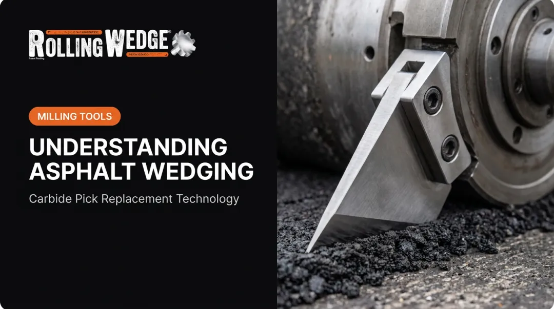
Rolling Wedge Milling Tools, an alternative to conventional carbide picks, carry nine carbide teeth on each tool, and each tool rolls over and away from the surface instead of striking it. The geometry is built around the variable-load reality of pavement rather than a lab bench.
Rolling Cutting Action: From Contact to Material Removal
Rolling cutting action advances a tool through material using progressive contact, wedging, and lifting, not sliding friction or direct impact. The sequence looks like this:
- Initial contact — tooth meets the surface at a shallow angle
- Penetration — wedge drives in as the drum rotates
- Fracture — material fails in tension along the wedge line, not in compression
- Lift and separation — rotating tooth lifts the fractured piece away
- Release — tooth clears the cut as the drum keeps turning
Asphalt and concrete are far weaker in tension than compression—commonly about one-fifth as strong, according to Rolling Wedge. A tool that pries material apart along that weak axis needs less force than one that crushes or chisels through it.
That same tensile-failure idea shows up outside pavement work. A 1987 U.S. Bureau of Mines report on rock fragmentation describes a rolling disc as a "continuous wedge," distinct from drag-cutter tools that rely on direct dragging contact. The paper is rock-fragmentation research, not a pavement-specific comparison, yet it still shows rolling and dragging as different contact mechanisms—not two names for the same motion.

Rolling Action vs. Conventional Carbide-Pick Behavior
| Factor | Rolling Wedge Milling Tools | Conventional carbide pick |
|---|---|---|
| Contact pattern | Progressive rolling contact | Direct strike or drag |
| Force transfer | Tension-driven fracture | Compression/impact-driven fracture |
| Wear exposure | Nine carbide teeth per tool | Concentrated at a single point |
| Vibration | Lower (smoother roll-in) | Higher (hammer-and-chisel motion) |
| Tool replacement | Every 1–3 months (company data) | About twice weekly |
Rolling Wedge's rolling-wedging-lifting design applies this principle to asphalt, concrete, and mixed surfaces. Company testing and demonstration videos show teeth rolling into and away from material at a fixed mounting angle rather than striking it head-on. That smoother roll-in gives steadier forward movement with less bounce, and less fatigue for the operator.
Independent third-party wear-rate testing on paved surfaces is still limited industry-wide. Treat efficiency claims from any manufacturer as provisional until you see the test conditions behind them.
Applying Geometry to Asphalt and Concrete Milling
Before swapping tool geometry on a milling drum, run through a quick checklist:
- Surface composition: pure asphalt, pure concrete, or a transition zone between the two
- Reinforcement: rebar, wire mesh, or unreinforced
- Cut depth: shallow texturing versus full-depth removal
- Machine type: Skidsteer attachment or large milling equipment
- Drum speed and feed rate: matched to tooth spacing and material hardness
- Target surface finish: texture requirements for the finished pavement
Use those answers to set wedge angle and cutting action for the surface you face. Harder or reinforced sections need geometry that lifts and fractures the material instead of grinding through it.
Reading the Warning Signs
Geometry problems show up as physical symptoms on the job site:
- Excessive vibration or bouncing
- Uneven cutting or inconsistent milled texture
- Rapid, concentrated edge wear
- Frequent tool changes
- Noticeable heat buildup or stalled forward progress
When these signs show up, reassess wedge angle and cutting action before wear accelerates or the drum takes damage.
Rolling Wedge builds Milling Drums and Milling Tools that install on Skidsteer attachments and larger equipment, including Roadtec and Caterpillar platforms. It supplies the Milling Drum and Milling Tools, not the attachment or machine. Brand names indicate compatibility only; Rolling Wedge is not affiliated with these equipment manufacturers. Drum fitment, tooth arrangement, and operating parameters vary by machine, so verify specifications against manufacturer guidance before changing tools.

Contractors comparing costs can use Rolling Wedge's online Milling Cost Comparison Tool or call (309) 322-1600 to review replacement frequency, installation time, and operating cost side by side. Verify any projected savings against documented data or a case study for similar job conditions. For a Milling Drum or Milling Tools quote, contact Rolling Wedge.
Frequently Asked Questions
What is the rake angle of a cutting tool?
Rake angle is the angle between the tool's face and the reference plane, measured in the cutting-edge normal plane. Positive rake sharpens the edge; negative rake adds strength behind it. Wedge angle is separate—it measures the tool body itself.
How to determine rake angle?
Rake angle is measured against a defined reference plane and cutting direction, typically using a protractor gauge, optical measurement system, or grinder setup during manufacturing. Manufacturer specifications usually list the exact rake angle for a given tool.
What does a positive rake angle mean?
A positive rake angle means the face angles away from the material, creating sharper geometry that cuts with lower resistance and improves material flow. The tradeoff is reduced edge strength, since less material bulk sits behind the cutting edge.
When to use a negative rake angle?
Negative rake suits hard, abrasive, interrupted, or heavy-load cutting conditions, where edge support against chipping and fracture matters more than minimizing resistance. Reinforced concrete and rebar-heavy surfaces typically fall into this category.
What is the geometry of a single-point cutting tool?
A single-point tool has a rake face, a flank, and a cutting edge where the two meet, defined by rake, clearance, and wedge angles. Rotary milling tools use the same ideas, plus rotation, feed direction, and changing contact angles.
What are the angles of a cutting tool?
The three primary angles are rake, clearance, and wedge angle, which together sum to 90 degrees when measured in the same plane. Specific tool designs may also include inclination, side, back, axial, or radial angles depending on the application.